The rear spar components have all been drilled. It’s now time to assemble the front spar. This job is a bit more involved than the rear spar because the center section has a lot of stuff going on. There was a service bulletin back in 2014 (SB 14-01-31) for cracks that were forming in the horizontal stabilizer front spar. The service bulletin remedy, including new spar doublers to strengthen the part, are included in my kit as part of the normal build.
Here’s what the center section looks like all assembled:

There are 6 degree bends on either side of the center section that need to be made by the builder. Also, several of the parts require trimming for proper fit. The Front ribs (not shown in the picture above) need to be trimmed for left and right fit. Here’s the spec:
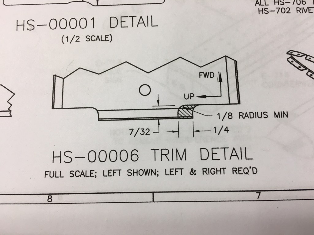
And here’s what my left rib looked like once trimmed. The one on the left has been trimmed to the required dimensions and the one on the right is unmodified.

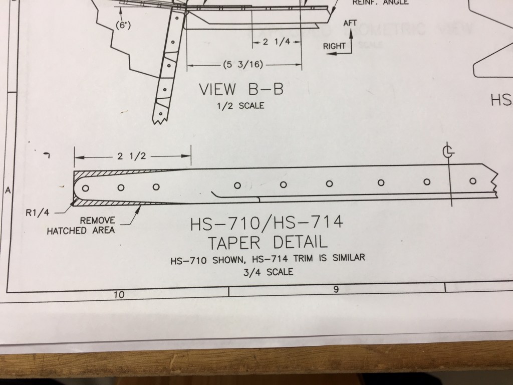
Likewise, the center reinforcement bars need to be tapered and rounded as well:

The center ribs and about half of the front spar channels are supplied by Van’s without rivet holes. These need to be match-drilled to the skin by the builder. This means that the horizontal stabilizer skins (sheet aluminum) are pre-drilled but some of the substructure is not. Once the skin is secured into place, the builder then match drills the holes in the substructure through the existing holes in the skin. This again insures a perfect custom fit.
The left and right skins are separate and are match drilled separately. To do this, I had to first assemble the skeleton:

Then cleco the skin to the skeleton. This takes some wrangling and a second pair of hands is very helpful.

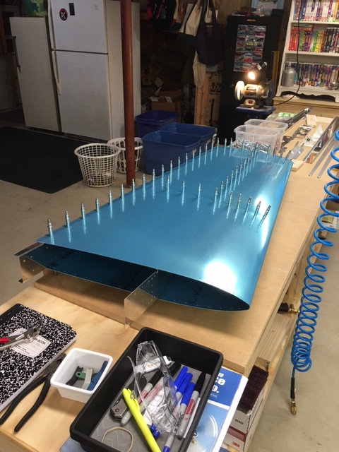
Here’s the complete right side all match drilled and clecoed, including both inboard ribs:

Once all the holes are match-drilled and resized (basically a drill bit is run through all holes), it’s time to take it all apart again so all of the holes and edges can be deburred.
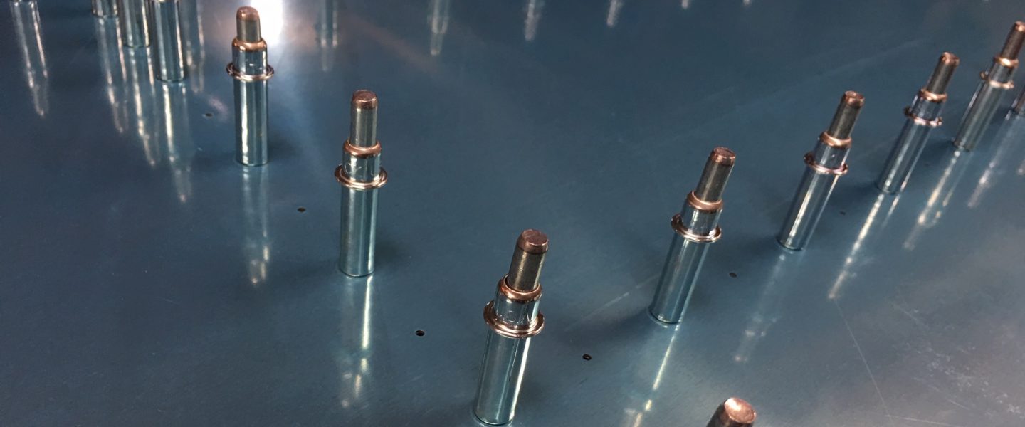
Here are all of the horizontal stabilizer substructure parts, deburred and ready for dimpling and priming:

