In order to align the fuel tank properly on the wing spar, the forward flanges of the Z-brackets need to be match drilled to the tank’s rear baffle. These are the Z-bracket flanges that are on the opposite side as those that were previously drilled and fitted with plate-nuts.
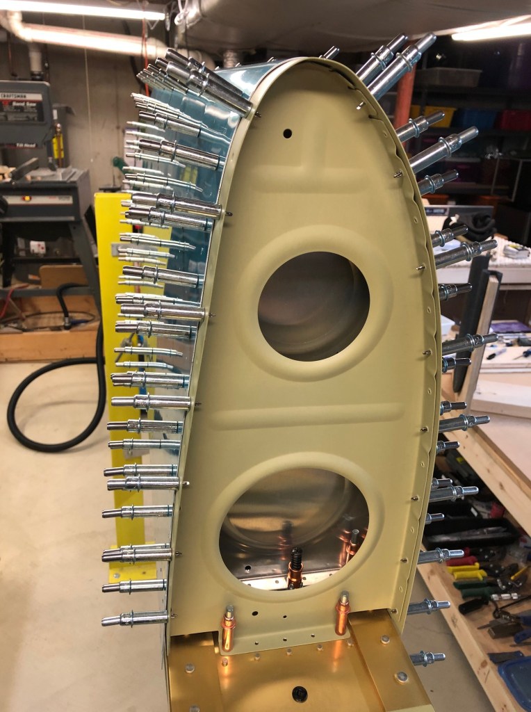
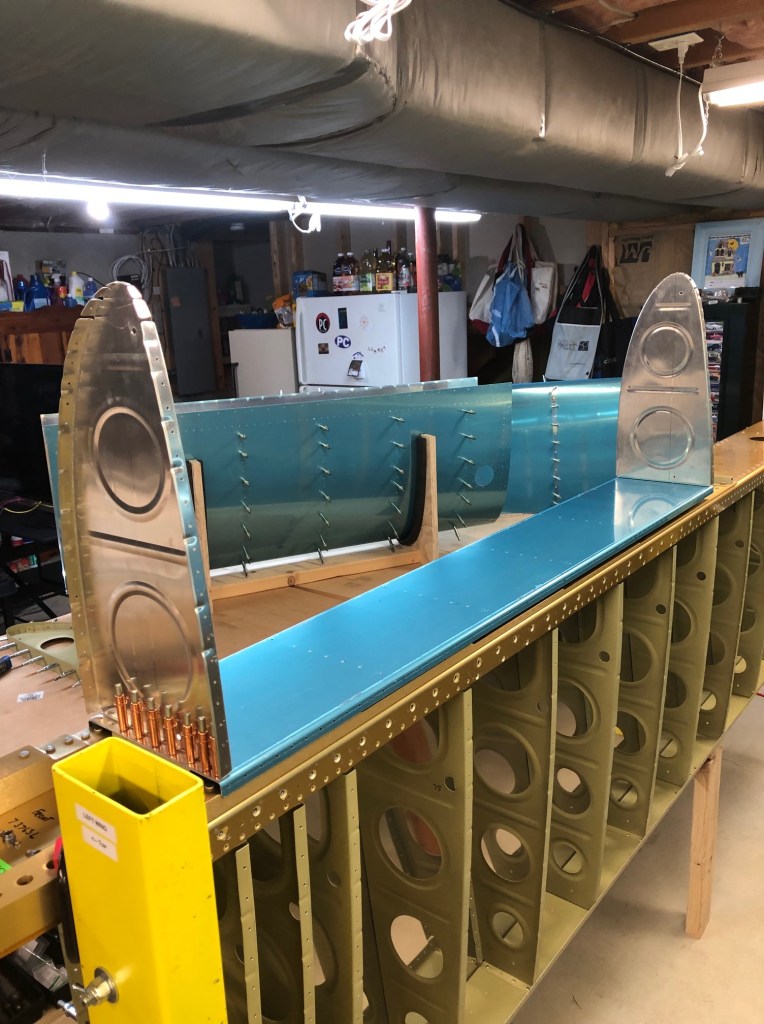
This task is begun by assembling the tanks with clecos in the leading-edge cradle. The tank skin, the tank ribs, and the rear baffle are all assembled together. Note that the aft flanges of the rib are not clecoed to the baffle. This is to allow room to install the tank on the wing and also to allow the ribs to be removed during the drilling process.
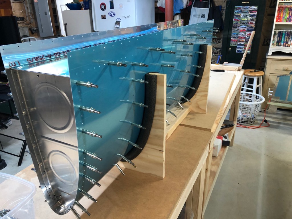
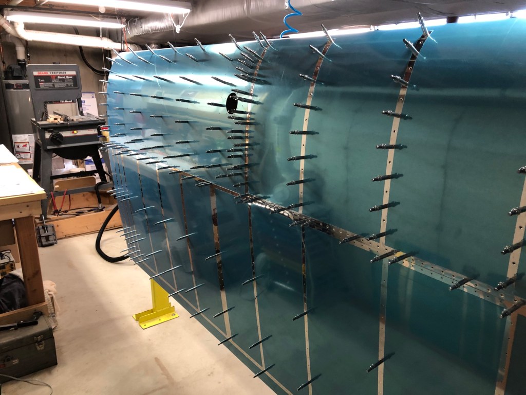
The assembled tank is then placed on the wing spar beside the outboard leading edge. This results in the complete wing leading-edge being in place.
The reason for assembling everything together like this is to get the tank properly aligned with the spar and outboard leading edge. Once the alignment is established and everything is where it’s supposed to be, then the tank baffle is aligned to the Z-brackets and is ready for drilling.
The only Z-bracket that is accessible for drilling is the #1 bracket, which is the inboard-most bracket. This bracket is drilled to the inboard tank rib and clecoed firmly in place.
With the #1 bracket clecos holding the tank in aligment, the outboard leading edge is now carefully removed from the wing spar. This exposes the outboard tank rib and the #7 bracket which is now drilled in the same way.
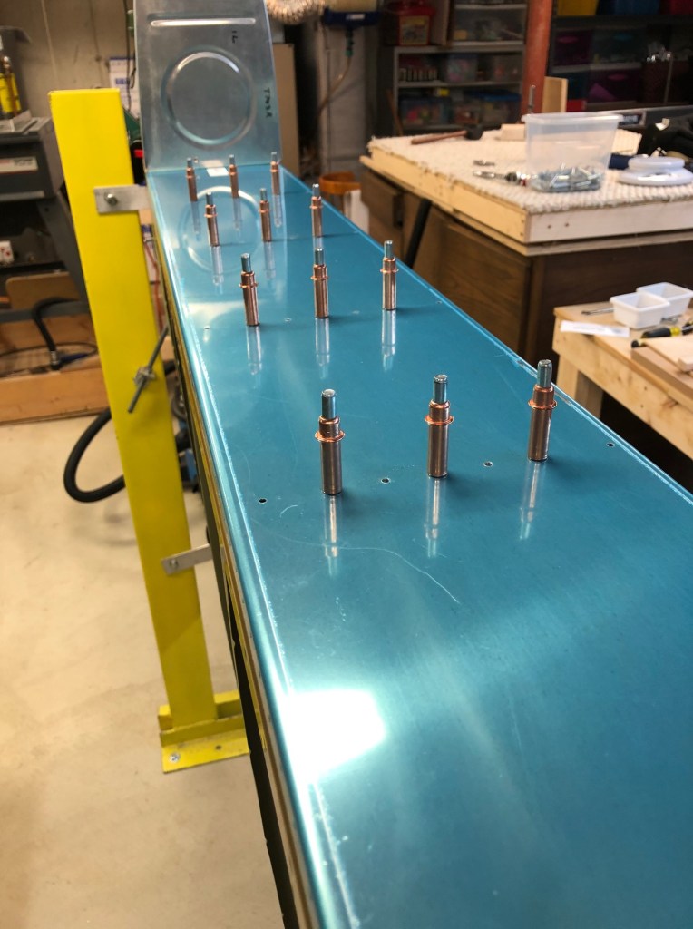
With the tank baffle drilled to the inboard and outboard brackets, the skin and interior ribs of the tank can be removed from the baffle, which remains in place with it’s desired alignment.
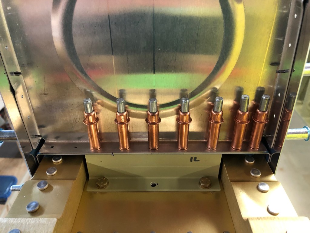
Now, all of the interior brackets can be match-drilled to the holes in the baffle to complete the job. Clecos are inserted as the holes are drilled.
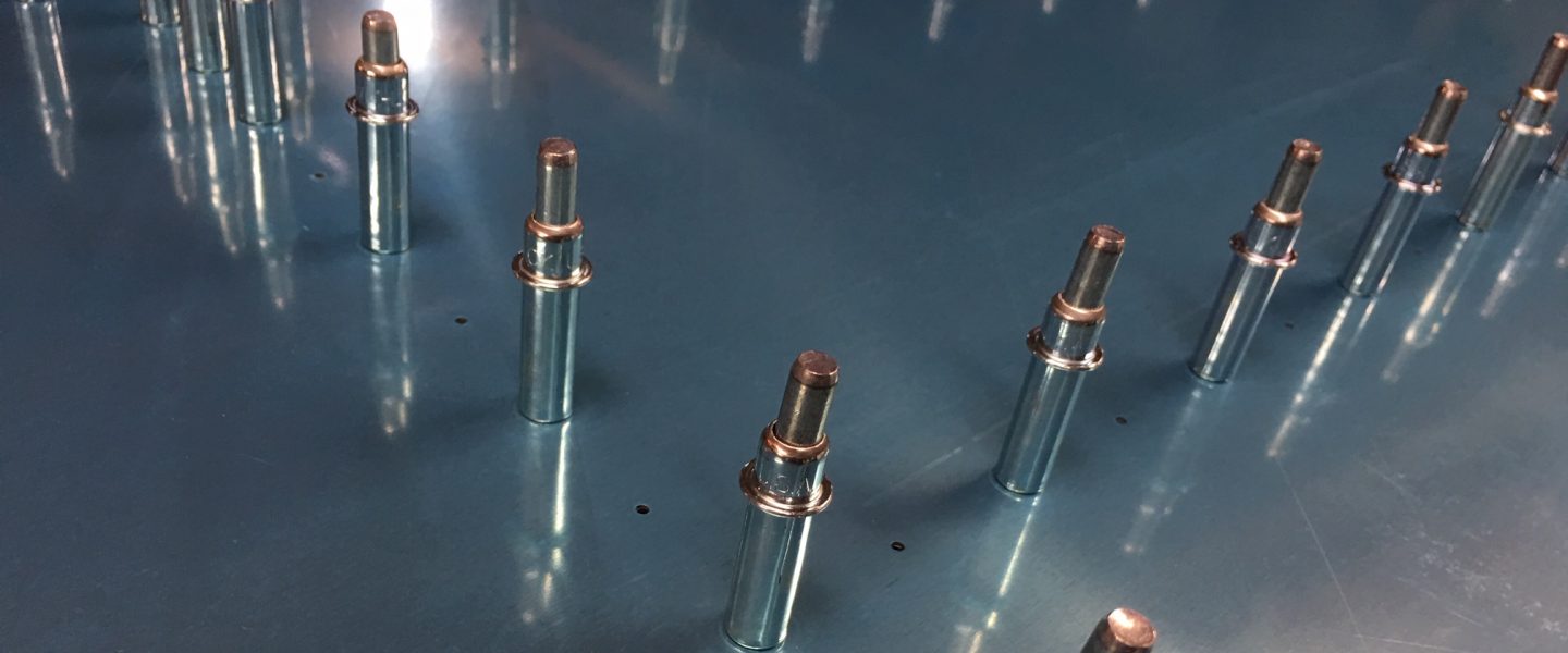
Once the drilling is complete, the tank can be removed from the spar and the bracket holes can be inspected. Of course, we already know from previous measurements that the holes will be well-placed on the bracket flanges.
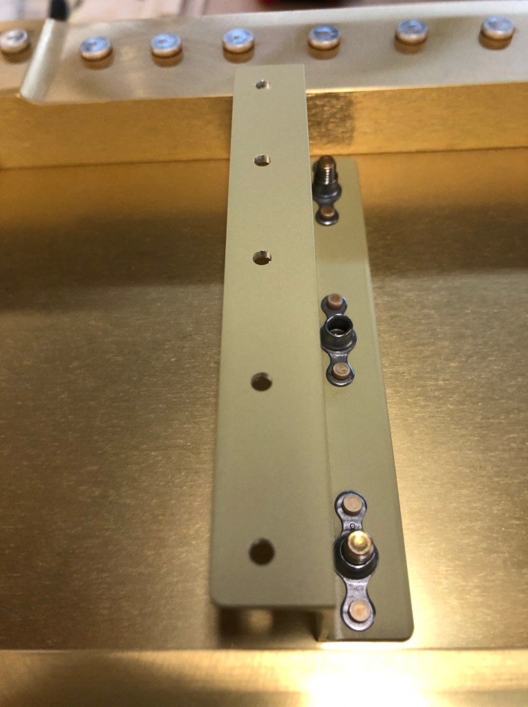
Note how the holes are slightly to the left of center, away from the Z-bracket web (the vertical component). This is by design and is a result of the way we originally located the screw holes as close as possible to the bracket web. These holes will be used to fasten the brackets to the tank baffle using blind (pulled) rivets. That extra space will be important in allowing room for the rivet puller point to fit behind the rivets. As it is, the rivet puller will still need to be modified to fit by grinding away some of the material on the point of the tool.
