Today’s building session was spent assembling the rudder, final drilling the rivet holes, and fabricating the lower fairing attach strips (R-918). The first task is to assemble the skeleton which includes the main spar, a lower rib, and the upper counterweight section.
The skins are then clecoed to the skeleton.
I had one fit issue when the skins went on. The fore end of the “D” stiffener comes up against the center hinge reinforcement plate with what I considered insufficient clearance since there is going to be a big 4-sized rivet head there. I removed the skins and shaved down both “D” stiffeners to provide a bit more clearance for the rivet.
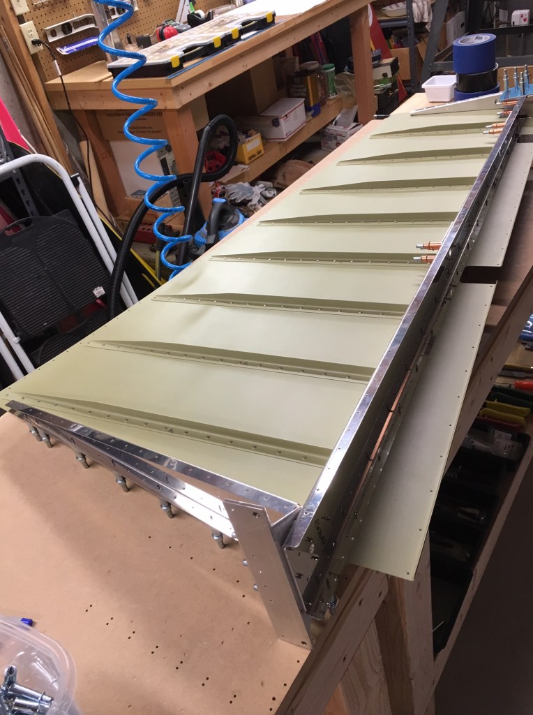
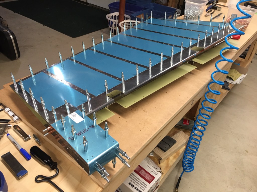
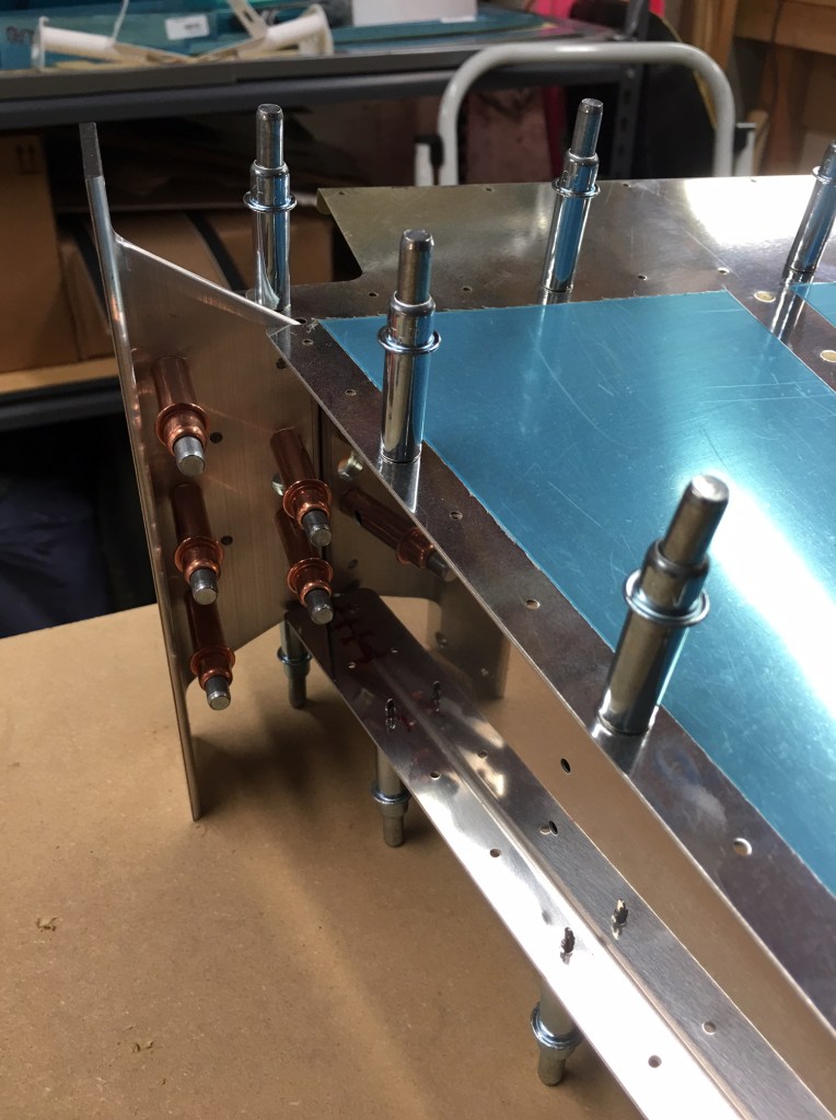
Here’s the whole rudder assembly clecoed together:
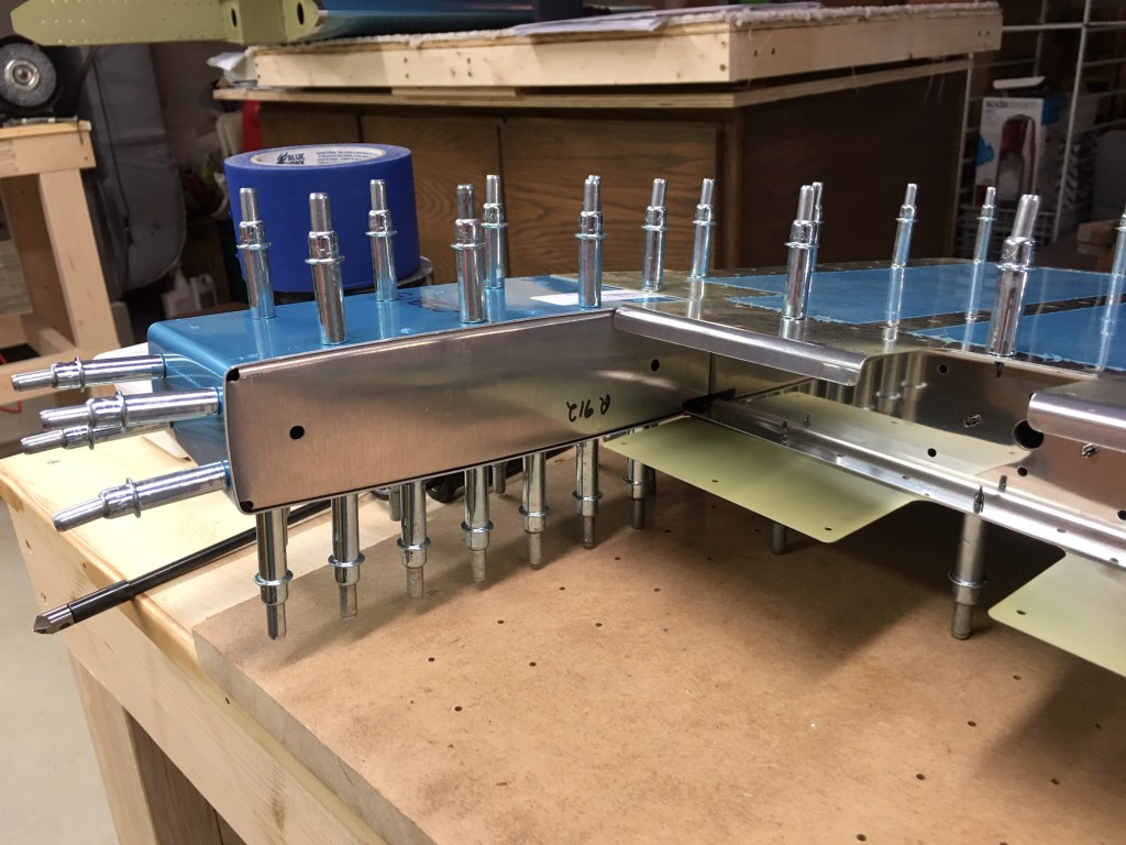
And the lower section with the rudder horn, which is the bar that extends out left and right for the attachment of the rudder cables coming from the pedals.
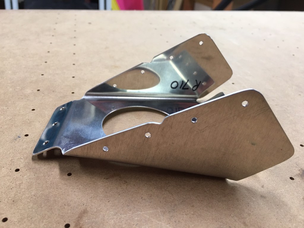
The R-710 rudder brace is a reinforcement piece that fits between the rudder horn and the lower brace. I’ve read quite a few blog and forum posts from other builders that had problems with this part and had to order sometimes two additional parts from Van’s so they could get it right.
The problem stems from the fact that the part, as shipped, has a lot of excess material that needs to be trimmed off. The drawings show the dimensions of what needs to be trimmed, and the part has holes drilled that appear to be along the required cut line. However, builders who used the holes as a guide often found themselves having cut off too much resulting in the drilled rivet holes being too close the the edge.
Wanting to learn from the mistakes of others, and not make my own mistakes, I cut well away from the guide holes and used the one-inch belt sander to grind away just enough remaining material to give a good fit. The resulting part looks like this:
The rivet holes along the top edges were match drilled to the skeleton and skin and they have just a little bit more than the required 1/4″ edge distance.
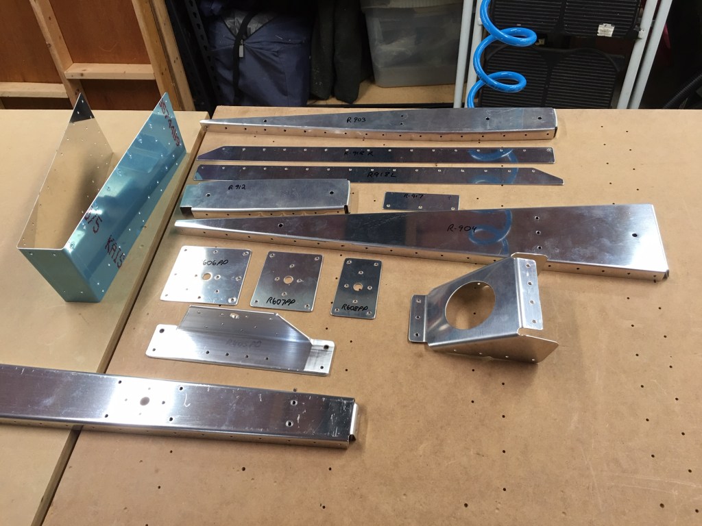
The plans then call for the fabrication of two attach strips for the lower fairing (the R-911 Rudder Bottom).
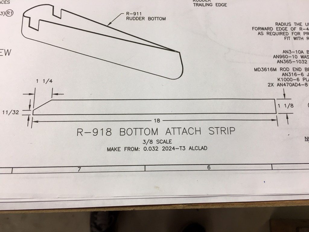
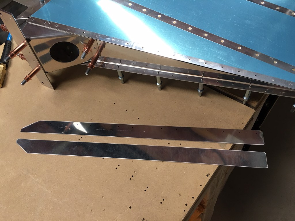
The attach strips are cut from aluminum stock supplied with the kit.
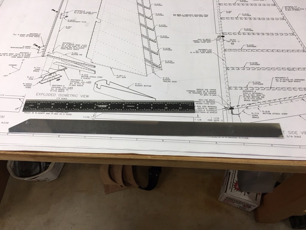
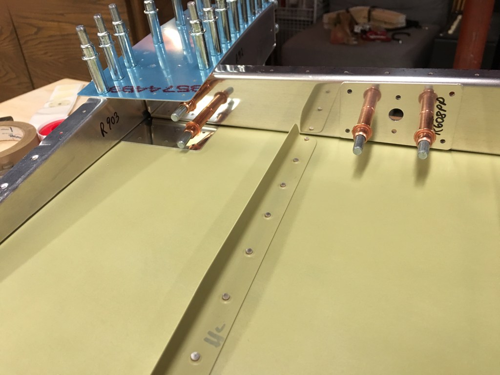
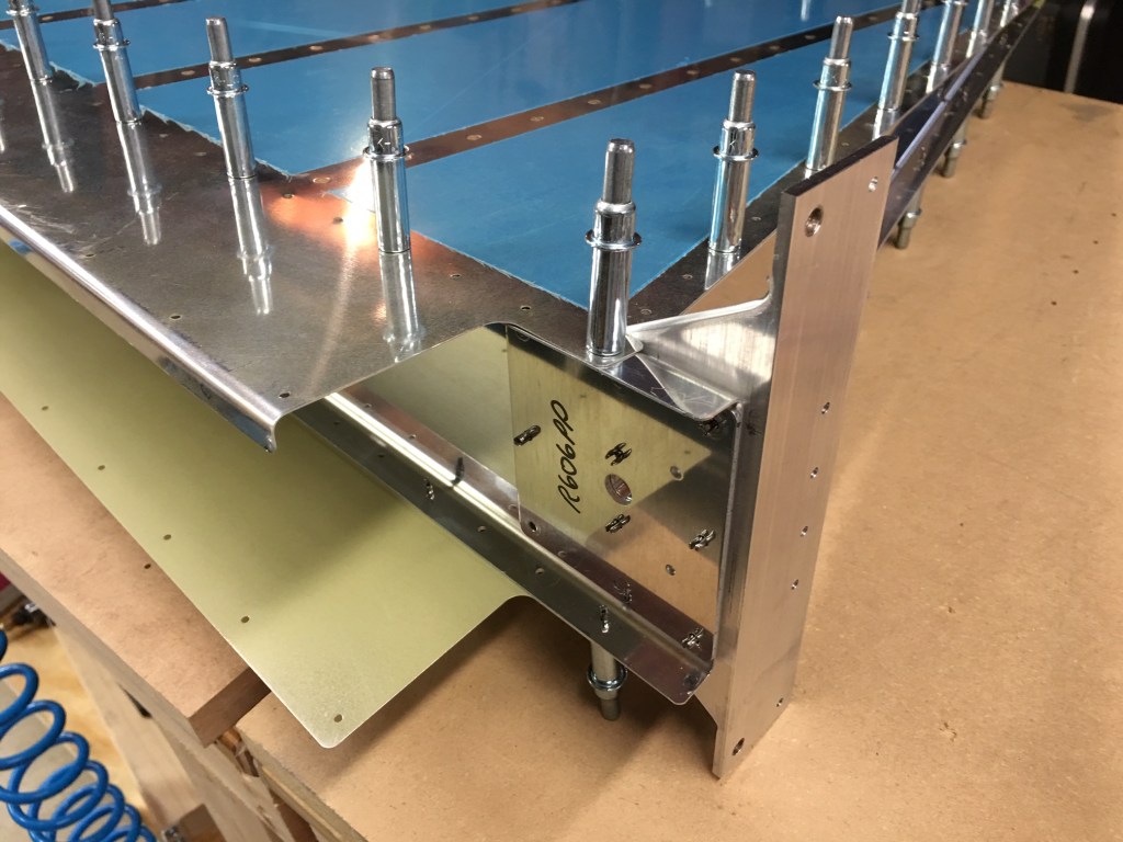
Here are the two strips, ready to be clamped to the lower rib for drilling. You can also see the R-710 rudder brace mounted between the rib and horn.
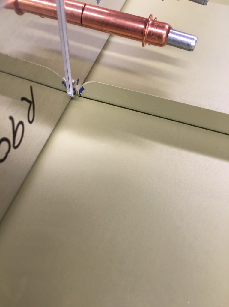
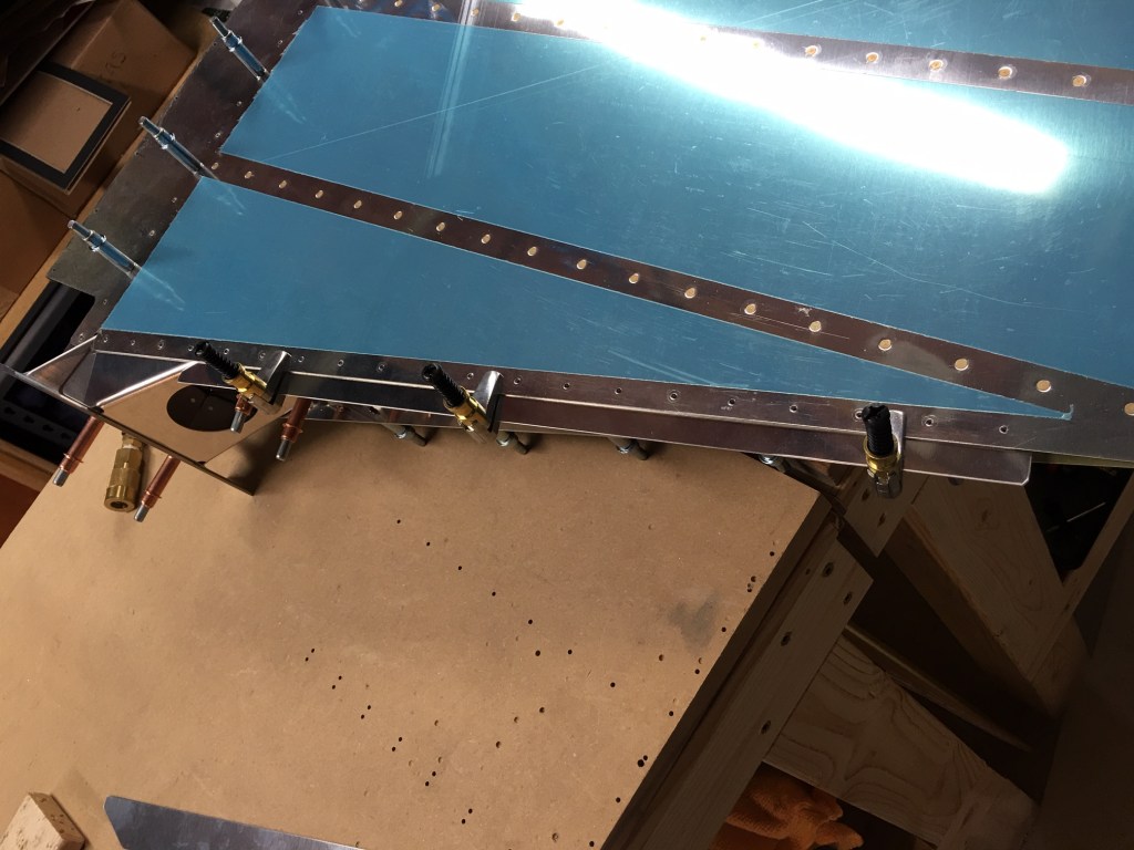
Here is the left attach strip clamped in place to be match drilled to the holes in the rib and skin:
The entire rudder assembly has now been final drilled, disassembled, and deburred. The next steps are to put together the counterweight assembly on the top/forward part of the rudder.