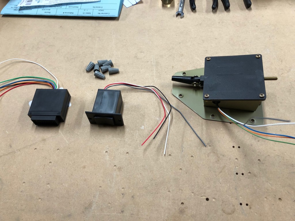
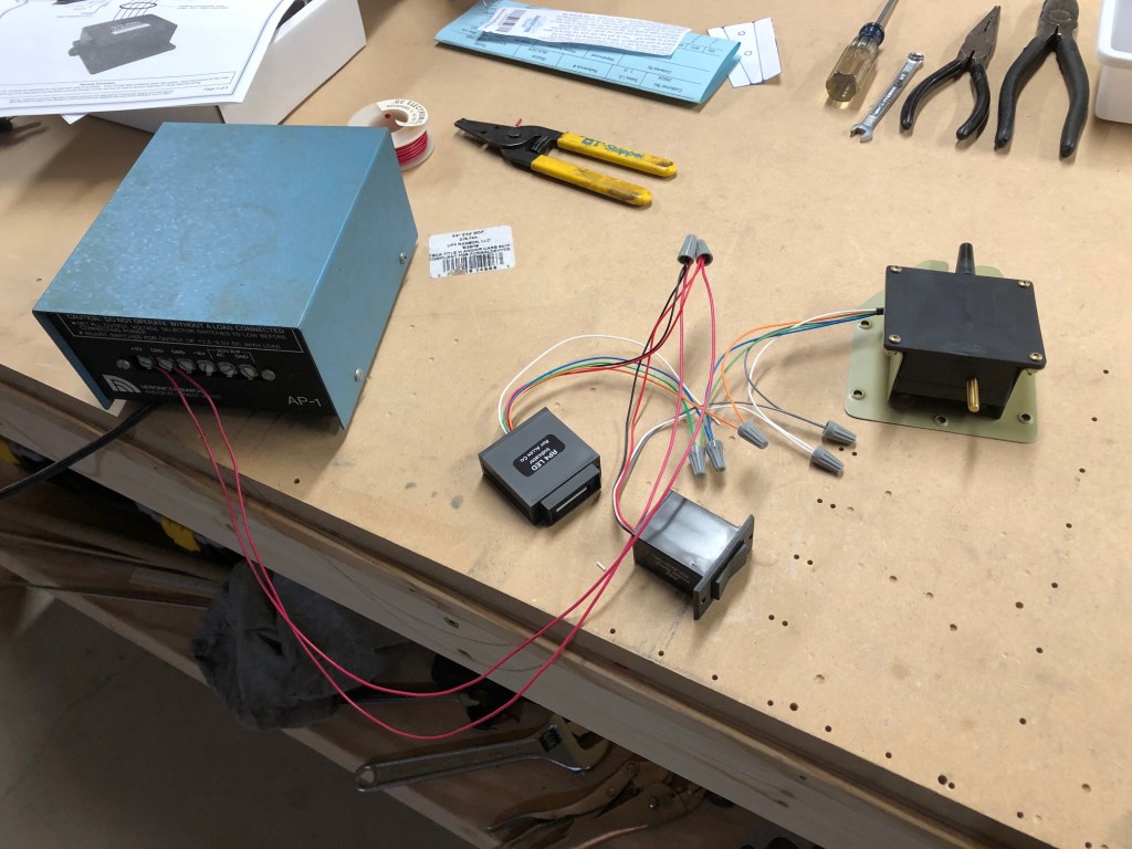
In today’s build session, I set up the elevator trim. This task started with the temporary wiring of the electric trim servo to the trim switch, the trim indicator, and a 12 volt bench power supply.
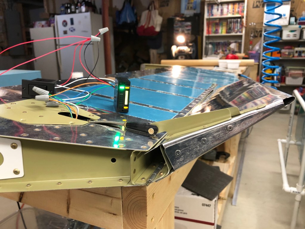
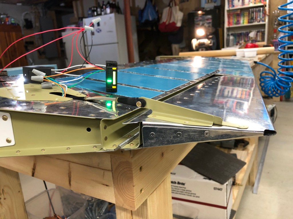
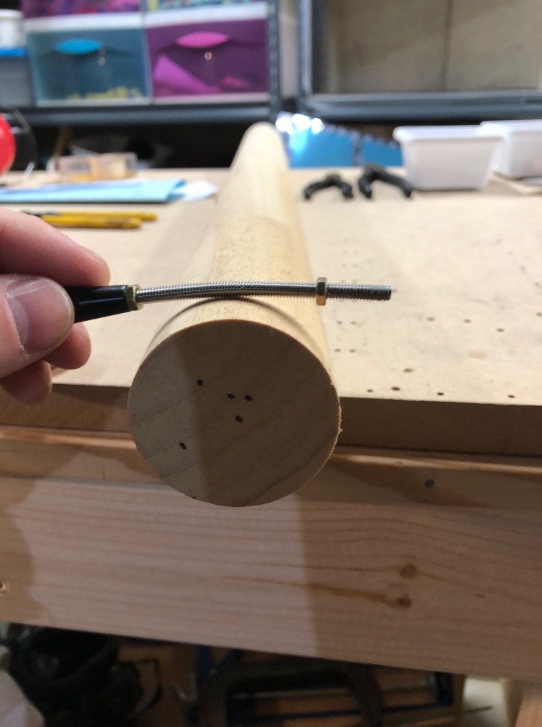
The entire assembly was then installed in the underside of the left elevator with the threaded rod installed in the clevis on the servo. As you can see, the rod is much too long and will need to be trimmed.

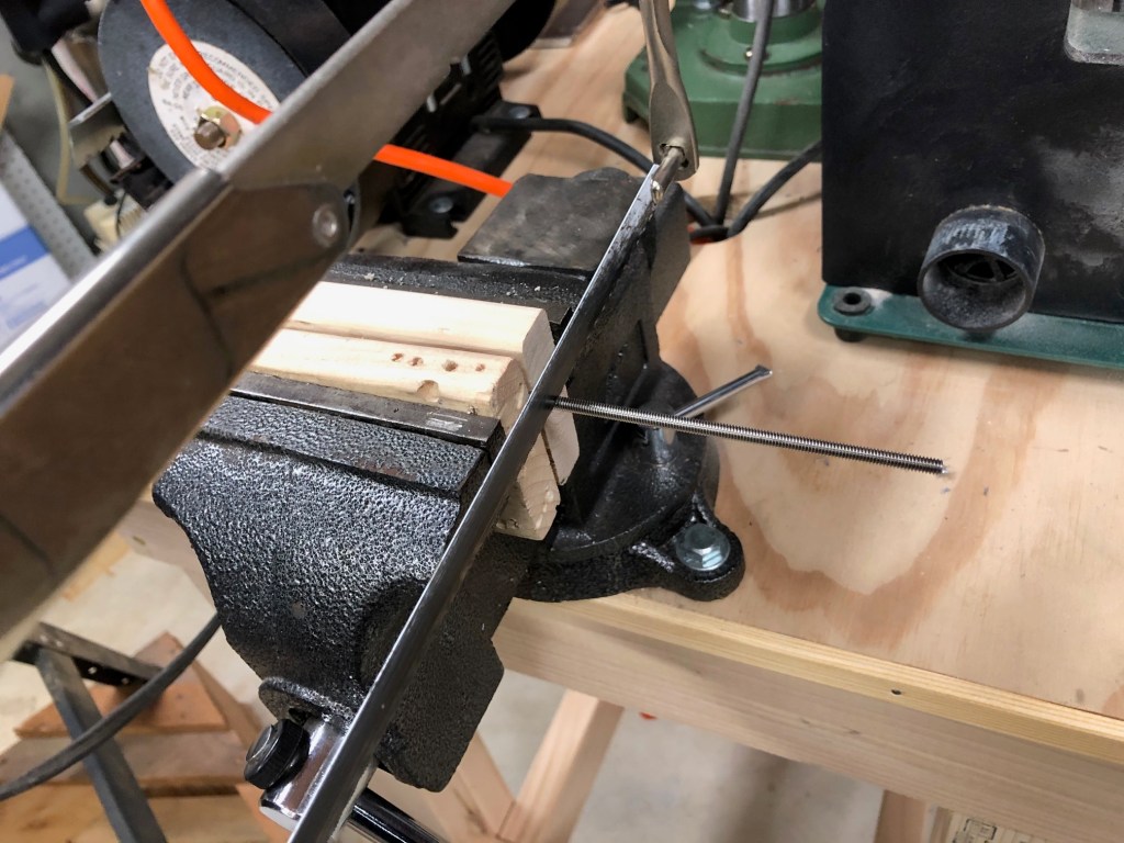
I set the servo to its center position and held the trim tab in-trail (trim-tab and elevator trailing edges aligned). This was my starting point for marking the rod for cutting. I then cut the rod to size with a hack saw.
With the straight rod, there is very little clearance between the rod and the skin of the elevator. Vans says that the opening in the elevator can be elongated to provide additional clearance. I found that the lock nut on the clevis was contacting the surface of the elevator in the full-up position and decided to put a little bend in the rod rather than elongate the hole for clearance.
I was then able to make adjustments for maximum up and maximum down deflection of the trim tab. The throw of the servo combined with the geometry of the trim tab horn yields a total swing of 40 degrees. Vans says that the range of movement should be biased in such a way that there’s more up trim than down trim. I adjusted the length of the rod to give a range of 15 degrees down and 25 degrees up. The following pictures show the trim tab in full-down, full-up, and in-trail configurations respectively. Note that the elevator is upside-down on my bench so nose-up trim occurs when the trim tab moves up (down when mounted on the aircraft).